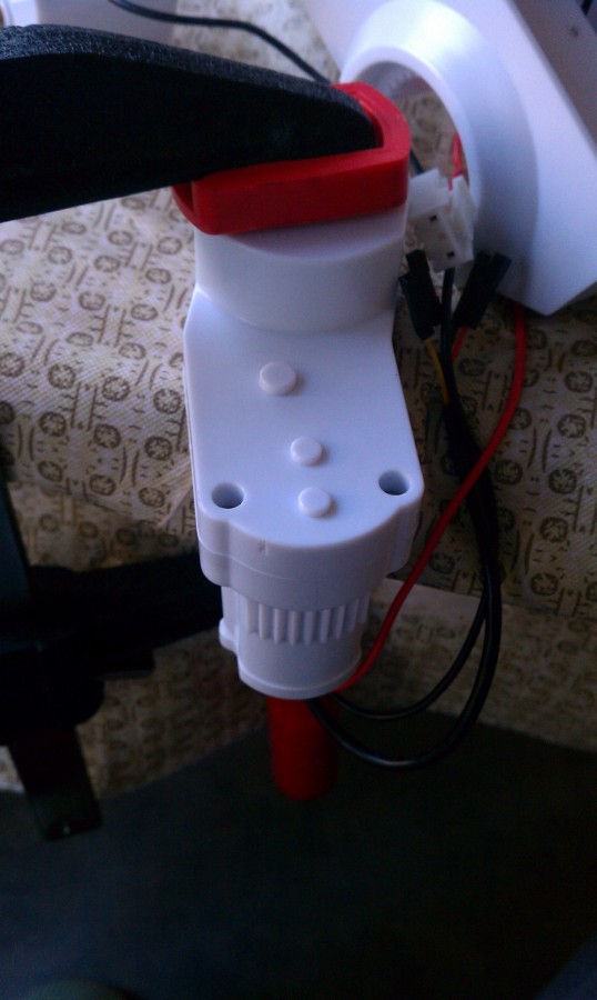
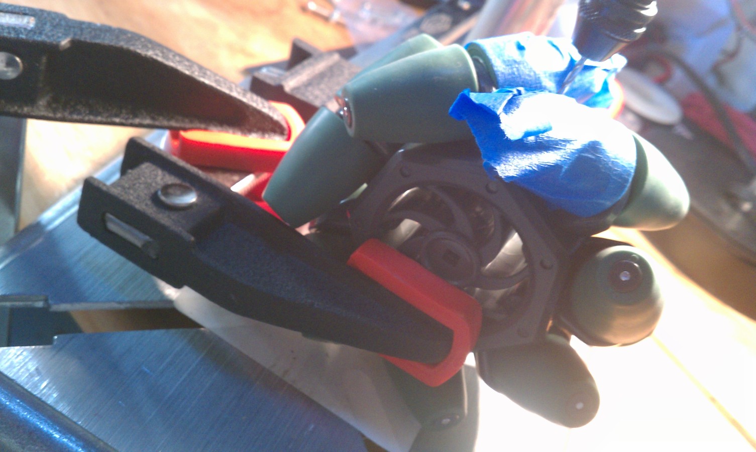
These photos show clamping down the roller (while still on the driveshaft),
and gently tapping on the driveshaft with any small metal rod to drive it
out (with some re-enactment required):
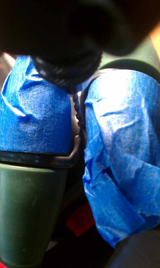
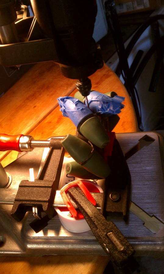
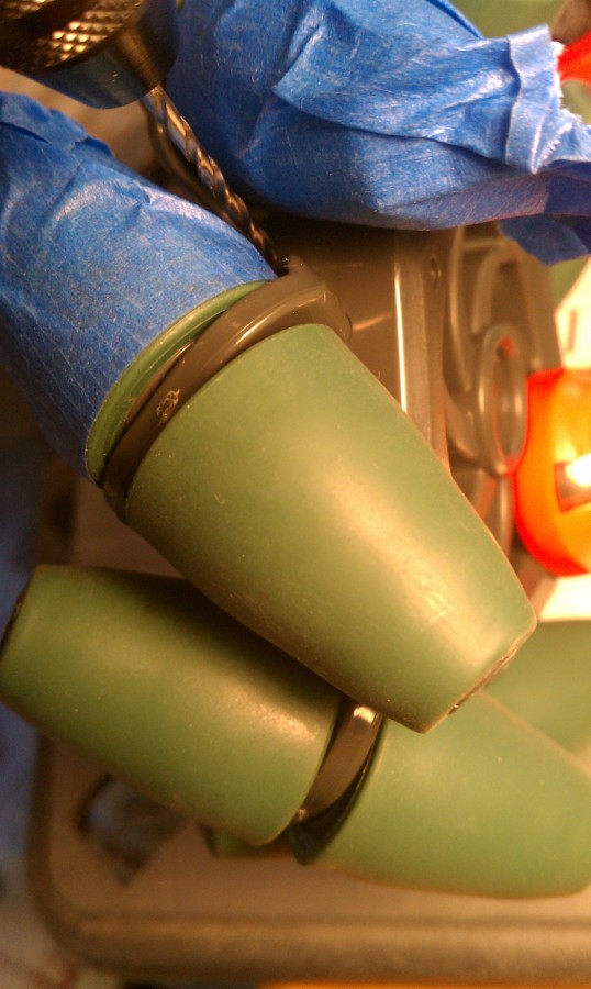
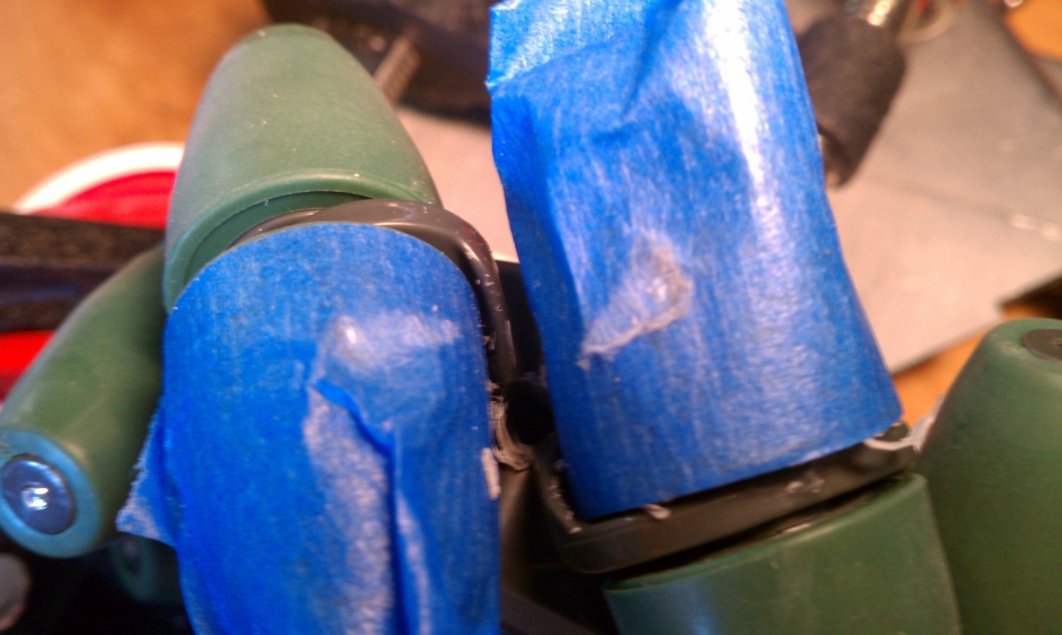
Drilling Setscrew Holes in Wheels
Here is how I drilled setscrew holes in the wheels. Note the tape applied to protect
them, and the scuffmarks from the drill on the tape in the last photo.
I copied this approach from Duane Degn's thread
here:
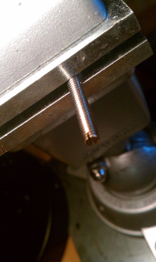
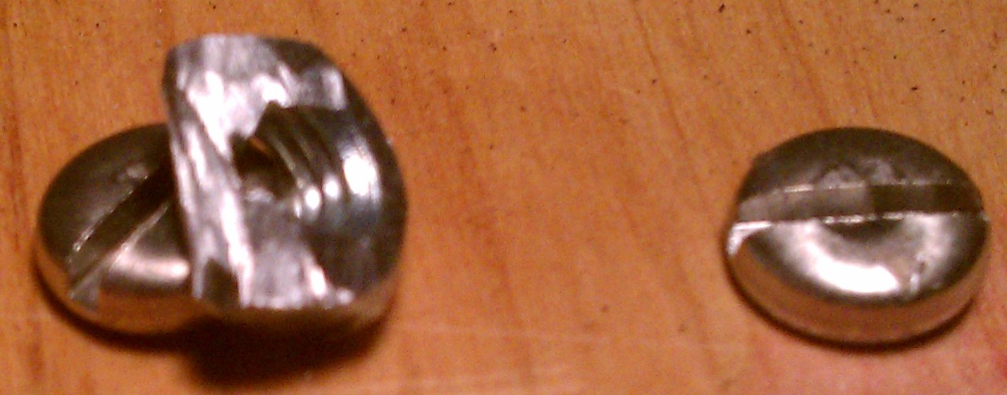
Finished Setscrew
This a finished setscrew, after I cut off the screw's head, and slotted it with
my Dremel tool:
Finished Triangular Nut
This a finished nut, which I had to cut into the shape of a triangle, in order to
get it to fit in between the wheel's spokes:
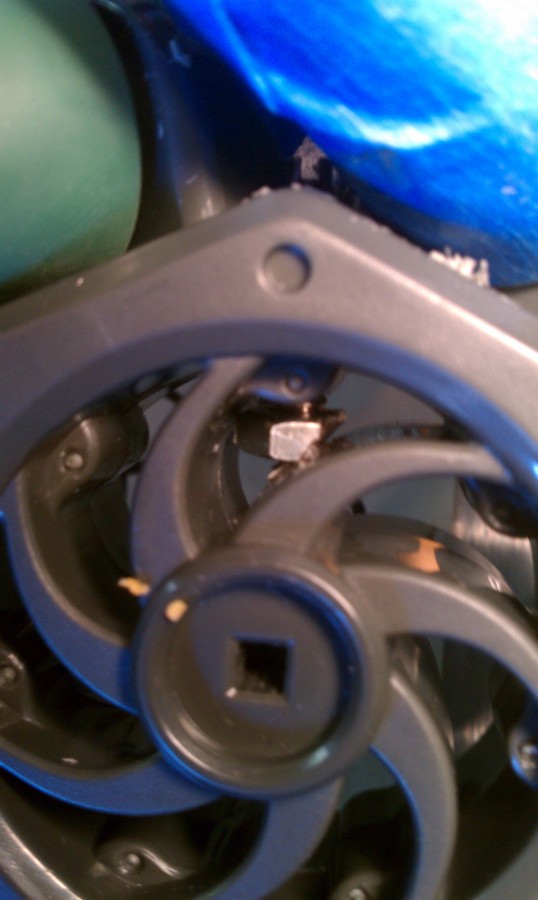
Setscrew+Nut installed in Wheel
Here is the setscrew and nut installed in between the spokes with tweezers:
Assembly Notes
For my VEX wheel setscrew construction, I used my Dremel drillpress, lots of
clamps, and a #50 drill to make pilot holes, then drilled them out with a hand
drill and a #21 drill. I drilled out the axle holes with the #21 drill as well.
This was for using #8x1-1/4" pan-head screws. To make the wheels more stable, I
wanted the biggest contact area I could get pressing on the driveshafts, so I
went with #8 screws rather than the #4 ones that Duane suggested.
Using my Dremel tool, I cut the heads off of them, then notched their tops, to
make them into setscrews. I ground the #8 nuts into triangles, to make them fit
in the tiny space between the VEX wheels' spokes.
I used the Dremel "waffle wheel" for grinding and heavy cutting, and the thin
"cutting disk" for cutting and notching the screws, because it's much thinner
than the "waffle wheel", so the former is best for making thin notches, i.e.,
to make a screwdriver slot.
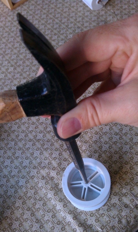
Lastly^2, I found that using a hammer and center-punch on the driveshaft, while
supporting the original Rover 5 wheel on the edge of a table, allows one to
remove the original wheels without pulling the driveshaft out of the motor's
gear assembly (which is a colossal pain to put back).
Lastly^3, I managed to put the two rear wheels on backwards. The symptom of this
is that even with correct wheel-rotation code, the robot will just pinwheel around
one wheel, no matter how the wheels are turning.
Electrical Notes
I found the Motor Encoder Lead Color Code in the Rover 5 doc:
RED is +5V for the encoder:
BLACK is 0V (ground)
WHITE is signal A
YELLOW is signal B Encoder Docs
I had to reverse some of the Motor Power and Encoder leads to make them consistent
with the silkscreening on the board, and with each other (read: the color code
above wasn't strictly followed).
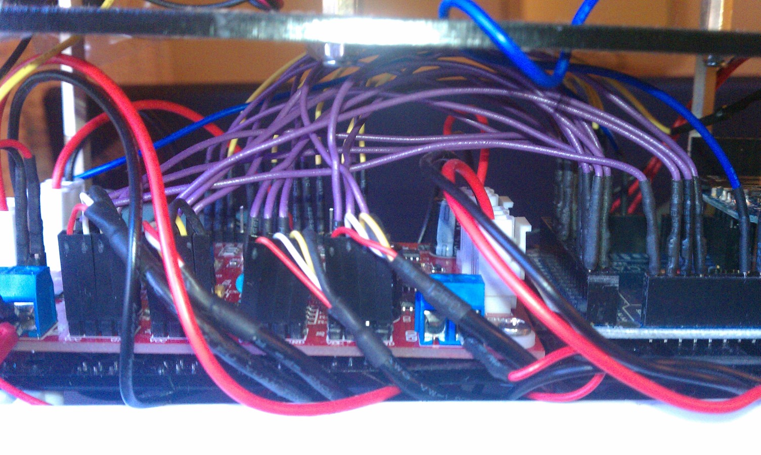
Left Side, showing Encoder Wires coming from Motors
This shows the wires from the motors connecting to the Motor Controller, and the
Motor Controller's Encoder and INT outputs going to the Arduino Mega2560 (the
thick red+black wires in white connectors in the middle are the Controller's outputs
to the motors):
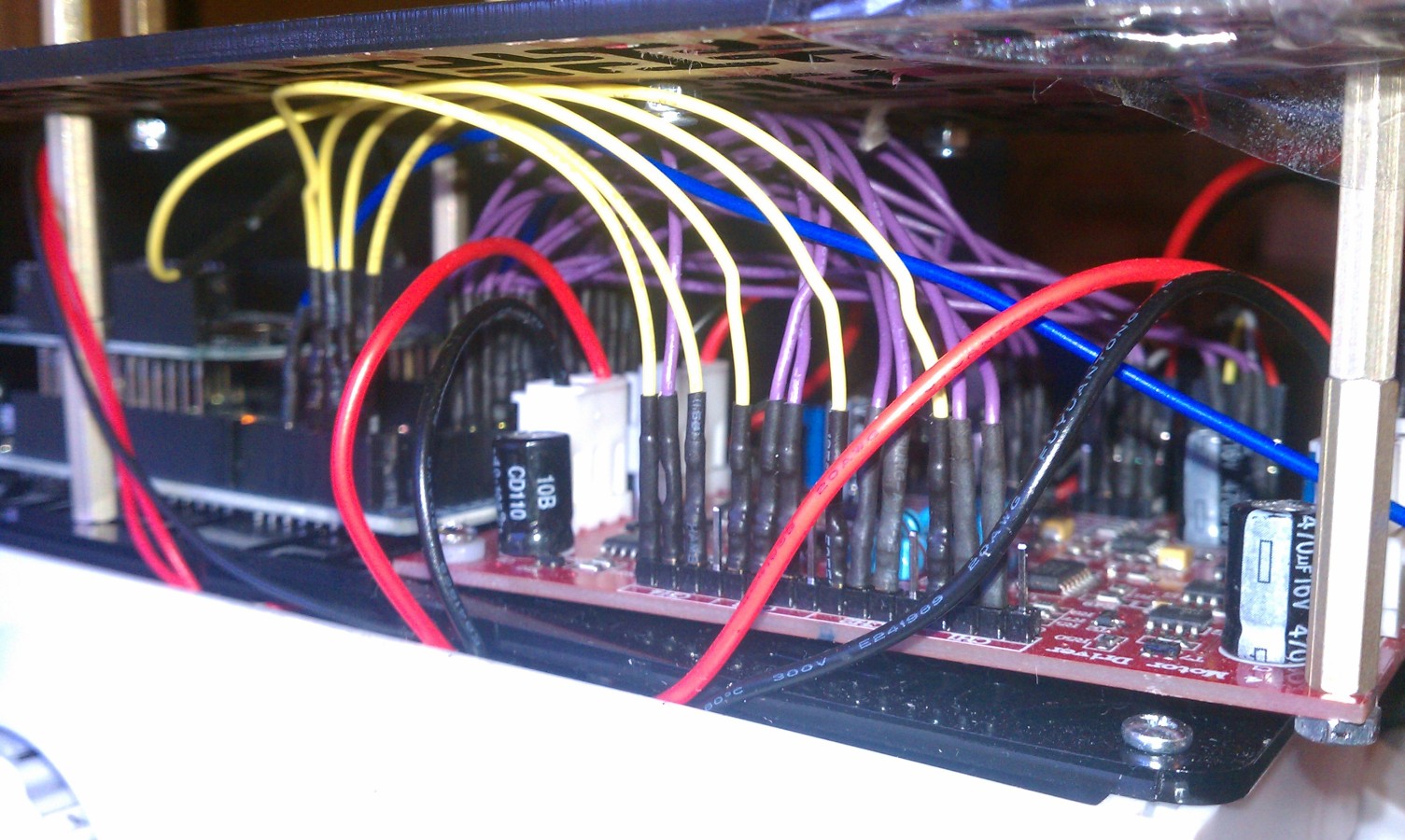
Right Side, showing Arduino Mega2560's PWM and DIR outputs connecting to the Motor Controller:
This shows the PWM+DIR wires from the Arduino Mega2560 connecting to the Motor
Controller (the thick red+black wires in white connectors in the middle are the
Controller's outputs to the motors):