Debugging Selection of Rover5 EncoderBands

I'm friendly!
Debugging by comparing EncoderBand plots vs. displaying them on the MotorSliders
Below is the "Virtual Joystick" GUI that I use to navigate the Robot. It's also used to test and develop new wheel speed control algorithms to accomplish the simultaneous Rotate and Translate capabilities that Mecanum wheels are capable of.

The Blue arrow: Chassis heading.
Red arrow: Chassis motion direction.
Magenta arrow: Points to the center of revolution about a fixed point.

You drive me crazy!

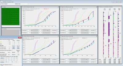
Below is a detailed screenshot showing the speed-change ramps that I'm evaluating. My goal here is to be able to execute the most accurate rotation + revolution + translation maneuvers that Mecanum wheels are capable of.

You drive me crazy!

The movie below shows the various aspects of the Robot's Steering GUI:


Legend:
Upper-left green window:
    Raw motor PWM values for all 4 wheels.
    This window has recording and playback capabilities.

Top-center window:
    The current PWM values sequence being played for each wheel.

Center 4 windows:
    Similar to the top-center view, in graphical form.
    The graphs' Y-axis is wheel RPM.
    Their X-axis is the PWM value require to accomplish that RPM.

Lower-left window:
    The Robot's steering GUI:
         The upper-left radio buttons select the type of motion.

         The center-left Directions field:
             Blue: Chassis is pointed in this direction
             Red: Chassis is moving in this direction
             Magenta: Points to the center of the turn currently being driven

         The center arrows:
             Dragging the mouse in this area moves the arrows.
             Radius constrols speed, direction is as indicated.
             Note: The relationship between the motion direction and
                 which way the chassis is pointing can be constantly changing.

             The black dashed circle indicates the maximum speed,
             driving straight forward or back.

             The red dashed circle indicates the maximum speed as reduced from the
              black max. speed circle, by an amount depending on how far away
              the current motion is away from straight forward/back.

             The orange dashed circle indicates a further reduction in the
             max. speed, by an amount due to combining rotation and translation.

         Mouse Drag Auto-Generation Controls (center-bottom of the movie):
             Controls for creating debugging data sets for wheel motions that are difficult
             to create by hand with the mouse.

         Settings File Suffixes to Load (far lower-right of the movie):
             Controls for playing back recorded data sets for further testing.

Back to Main Page...