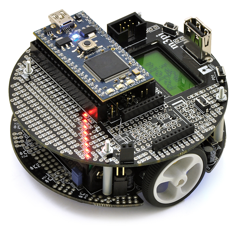
The m3pi has a microController "downstairs" that controls the wheels, reports the Battery Voltage, etc.,
The mbed microController "upstairs" uses its p10&p9(RX1&TX1 UART) pins to communicate with the "downstairs" microController.
The mbed microController uses its p27&p28(RX2&TX2 UART) pins to communicate with the XBee Radio.
Alas, while planning how to connect a LSM303D 3-Axis Magnetometer (Compass) to the mbed microController, I discovered that the above means I have no I2C pins available to use to query the Magnetometer, as shown in the mbed's pinout diagram:
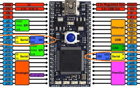
Here is the mundane pinout diagram of the mbed microController, with the problem pins circled:

Solution:
Luckily here, I found that there is a SoftwareI2C Library available here, that can do I2C on any two unused Pins, so I thought I'd try that out.As a learning experience though, I decided to re-write the I2C library and hopefully improve it, with the results shown here (scroll to the right to see more of the screenshot):
My Arduino is so slow, in the Logic Analyzer I saw that I needed to smash "lost time" out of the code in as many places as possible. This code reflects my efforts to do so everywhere I could spot "wasted time".
The unwanted "stretch-out" delays that I saw in the the Logic Analyzer showed me which parts of the code needed these enhancements.
I.e., in readBytesFrom(), I unrolled a for() loop that reads between 2-6 bytes, replacing it with an "intentional fall-thru" switch() statement instead.
More broadly, I replaced many duplicate single lines of code with one-line inline functions, to increase readabilility and maintainability while removing unwanted "stretch-out" delays added by function calls.
I checked that these "stretch-out" delays were no longer present in the Logic Analyzer output to confirm that my fixes were successful.
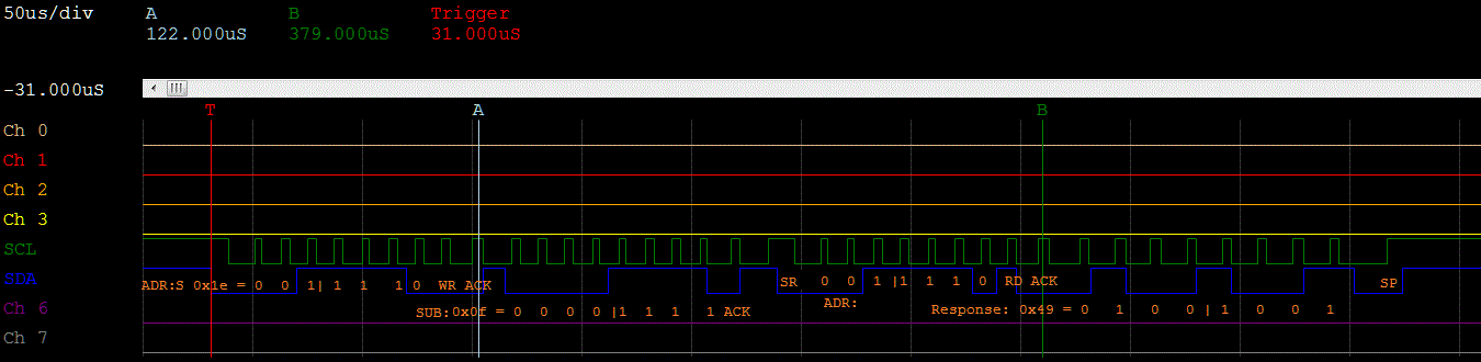
The Logic Analyzer screenshot above shows a complete I2C conversation, that requests and reads the contents of the LSM303D's WHO_AM_I Register. This sequence consists of the following:
0. Clock out a START condition (= "S").
1. Clock out the LSM303D's address: 0x1e,
followed by a WRITE(=0) bit.
2. Receive an ACK bit from the LSM303D.
3. Clock out the WHO_AM_I Register's sub-address: 0x0f.
4. Receive an ACK bit from the LSM303D.
5. Clock out a Repeated-Start condition (= "SR").
6. Clock out the LSM303D's address again (0x1e),
this time followed by a READ(=1) bit.
7. Receive an ACK from the LSM303D.
8. Receive the LSM303D's response, which is the 1-byte contents
of its WHO_AM_I Register (= 0x49).
8. Clock out STOP condition (= "SP").
The source code for my re-write of the I2C-on-any-GPIO pin driver is here.
I heartily encourage and welcome feedback on how I can improve it.
The explanation above is an excerpt from my UCSC Extension class's Final Project report.
My full Final Project report can be read here.
Back to Main Page...