This Project incorporates experience that I gained from these previous Projects:
Two movies of it moving Diagonally and Laterally are here (scroll down to the bottom of the page)
• Embedded SWD: Infrared Remote Record/Transmit using MicroController Timers
My latest Robot is the Class Project for my UCSC Extension class e4357, Embedded Firmware Essentials. For it, I wrote mbed MicroController code running in a m3pi Robot to collect data from its 3-Axis Magnetometer (Compass), to implement its Autonomous Room Survey functionality.
This Robot is controlled by an ARM Cortex-M3 in a NXP LPC1768 package. This class project is described here, and its supporting Project files are here.
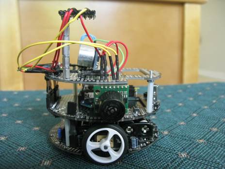
The Robot and its Remote Control started out as this simple implementation, communicating via XBee:
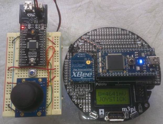
The Joystick Radius value specifies one of 8 Speeds, from very slow up to ridiculously scary fast.
The Joystick Theta value is between 0-15. It can specify Forward Motion, Backward Motion, or one of 3 different Turn Radii as shown here:
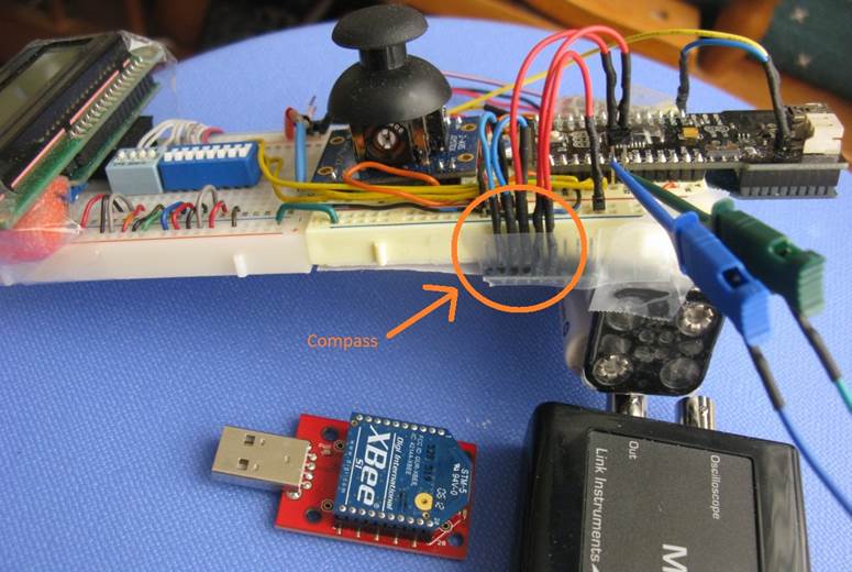
As the class progressed, the Remote gained a Display, 12 DIP Switches, and a Compass.
The Switches specify which Functions to run and the Arguments to be passed to them.
The Remote's Compass works in conjunction with the one on the Robot,
constantly sync'ing the Robot's R-Theta Coordinate System to the one on the Remote.
Thus when the Remote is rotated, the Robot rotates as well, ensuring that Forward
always means the same Absolute Heading on both devices.
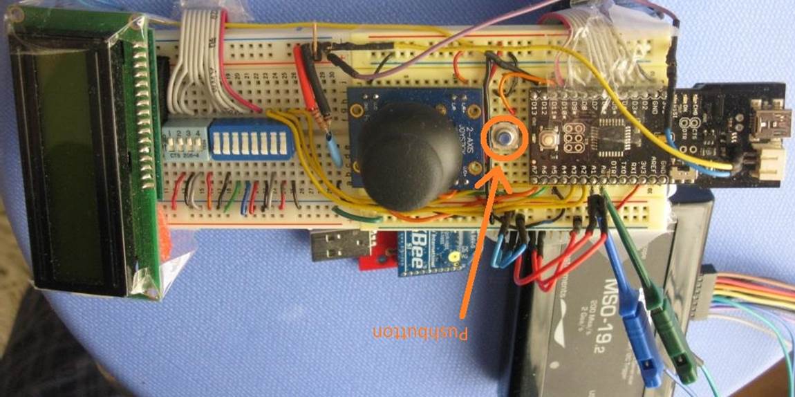
The Fio MicroController (on the right and top in the photos above) was chosen for its built-in XBee support on its back side, to simplify communication with the Robot’s XBee.
The DIP switches above modify the Robot’s Behavior.
By Behavior, I mean:
• How does the Robot Respond to various Stimuli, such as Moving Objects in its Environment?
•
How does it respond in order to persevere in the face of Goal-Blocking
Placements of Multiple Barriers in its Environment?
• Under various Sets of Conditions, in which ways does it Re-Prioritize its several Autonomous Goal-Seeking Behaviors?
The Switches’ fine-grained control of which Functions are Running in which Tuples with which Arguments facilitates faster Algorithm Design and Debugging.
Of the 12 DIP Switches, 4 select which Functions should run, while the other 8 specify Arguments to modify those Functions’ behavior, i.e., Fast vs. Slow Speed, Near vs. Far Wall-Following, Aggressive vs. Gentle PID Parameters.
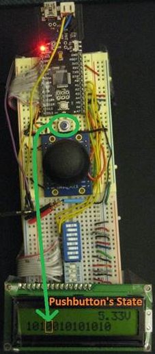
Each time the PushButton is pushed, all Functions are stopped and only those specified by the 4 Function Selection Switches are re-started, re-reading their Arguments Switches and thus updating their behavior.
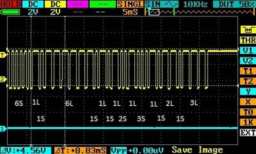
The black “MSO-19” box above is a Logic Analyzer that I’m using to debug my I2C Driver’s communication with the Compass.
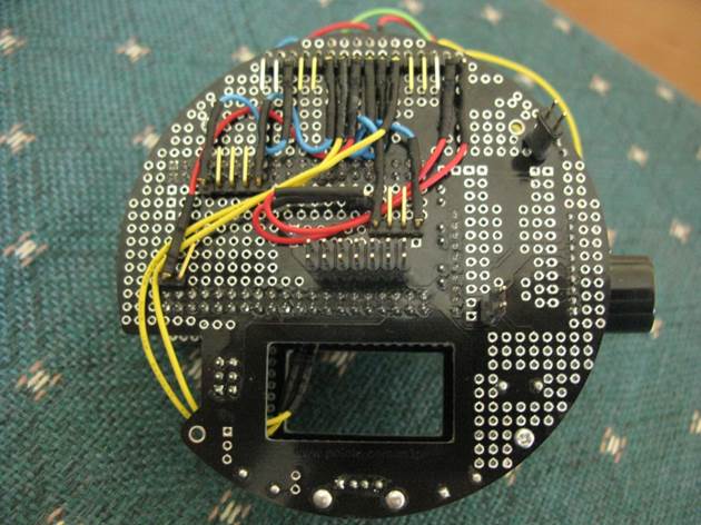
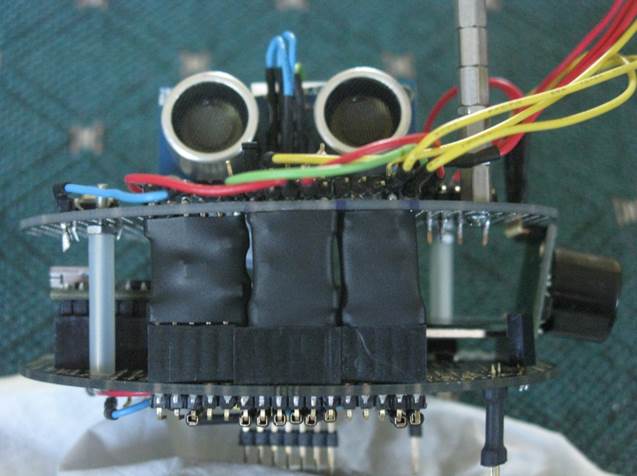
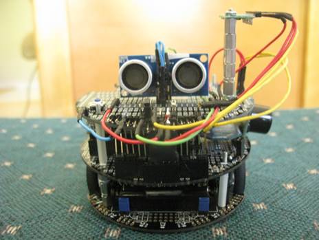
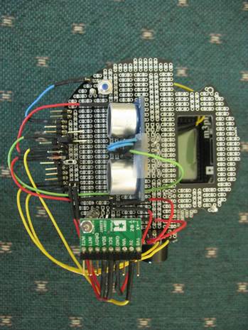
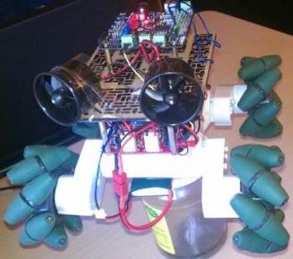
To support its Autonomous Room-Mapping functionality, the Robot gained a 3rd-floor to provide mounting space for Forward-Looking Sonar, Side-Looking Sonar, and a Compass.
It was challenging to route all the necessary signals from the Cortex-M3 on the 2nd-floor up to the 3 Sensors on the 3rd-floor. I installed Headers between the floors, to allow the 3rd-floor to be quickly removed so it can be worked on separately.